|
|
|
|
Accurizing and
detailing
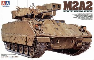
the Tamiya M2A2 IFV kit.
Tamiya
1:35
PART
2
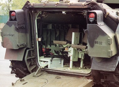
REAR OF THE VEHICLE
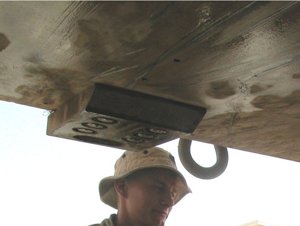
The loading ramp and rear door in it can both be attached open or closed, but as there is no interior in M2A2 kits, you should attach both closed, unless you want to scratch build your own interior (or use interior parts from older Tamiya or Academy M2 kits). Hinges for the ramp are workable, but slightly over scale because of this. Details on outer side of doors and rear ramp are quite accurate although a bit simplified - they could be improved with some photo etched parts, but currently there is no PE set available dedicated for M2A2 Bradleys. Parts form Eduard "exterior set" for M2 Bradley can be used here (and in other areas of the vehicle as well, although many parts in the set are not suitable for M2A2 variant). You may also want to replace the plastic towing rope with some metal one (I used Karaya brass rope in my model). Two heavy "steps" are bolted to the bottom of the hull of the real M2A2/M3A2 vehicles, under the loading ramp - these are not present in Tamiya kit, but very easy to add from a piece of styrene (see photos below).
 |
 |
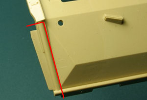
| Details of the "step" bolted to the bottom of the lower hull. | On
this photo you can see where two steps are attached under the loading ramp.. |
Two large stowage boxes have simplified hinge and lock details - again some PE parts could be used to improve this area. Taillights attached to the top of boxes have metal guards over them and these are much too thick in the model and are not quite correct shape. Mentioned Eduard PE set for M2 includes nice new taillight guards, but I made my own replacement parts from aluminum sheet. Under the stowage boxes are two rubber mud flaps. These are way too thick in the model and should be replaced with pieces of thin metal or styrene sheet.
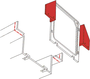
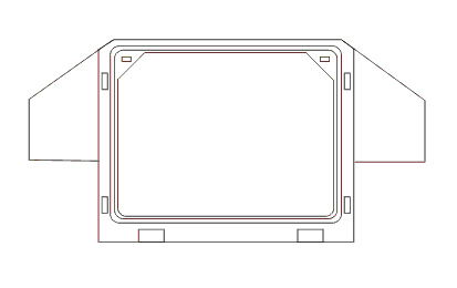
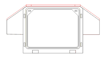
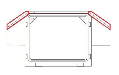
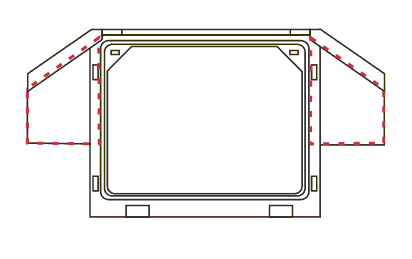
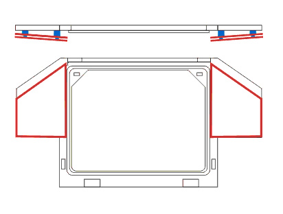
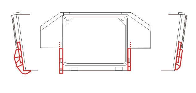
One of the major inaccuracies of the model is the way the rear armor plates (behind stowage boxes) look like. Tamiya simplified this area way too much. Heavy surgery is needed to parts B44, B26, B30 and E14 to make it all more accurate and some styrene sheets are needed. I was not able to find pictures that would clearly show this area, so below are my drawings based on what I was able to discover - there are still some question marks left however...
GO
TO PREVIOUS PAGE
GO TO NEXT PAGE
PART1 PART2
PART3 PART4
PART5 PART6
SUPPLEMENT
|
Most of the photos of real vehicles in this article came from various sources on the Internet. I have so many of them downloaded on my computer that I lost track of where each of them came from. If you recognized some of the pictures as yours and want me to credit you for them here, or you want me to remove them, let me know - I'll sure do it. |
![]()
![]()
![]()
Copyright © 2004 VODNIK, mailto:pawel@vodnik.net